
Many tutorials show how to do bare metal programming on a Raspberry Pi. Some are very good, but they tend to have a certain magic vibe on them. “Trust me, just use the following magic constants and it will work”. I can’t help but ask, hey, where did this magic come from? What if I wanted to figure out all details by myself?
This post describes my moderately successful attempt to find the sources of all information needed to create a very simple bare metal assembly program that sets one of the Raspberry Pi 3 GPIO pins to high (AKA 1 or “on”).
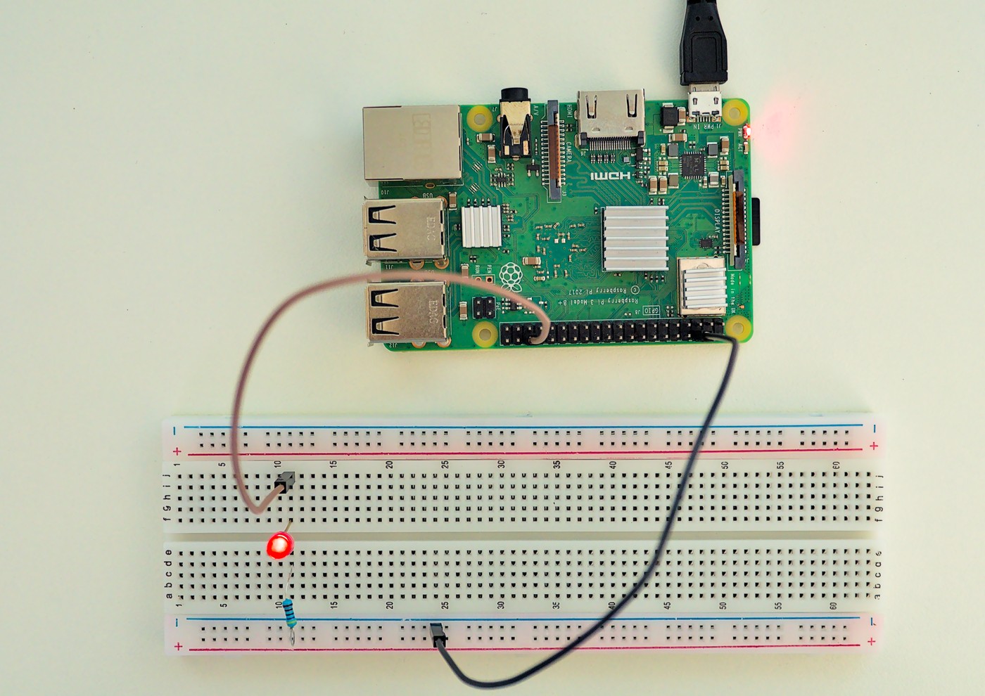
The program running in all its glory. LED attached to the GPIO pin to show it is really going high.
What’s the plan?
To me the beauty of bare metal programing is its conceptual simplicity. Gone are all the layers that usually stand between the code we write and the device running it. I know, these layers are there for a reason and more often than not I am glad they exist – but being able to look at a software system as a whole and (more or less) understand everything all the way down is very cool.
How simple is it? When a computer boots up, at some point it will start to look for code to execute at a certain memory address. All we need to do is:
- Find a way to get our binary code loaded into that certain address, so that the computer will run it upon start up.
- Design, write and build our code so that the resulting binary relies only on features provided directly by the computer itself.1 Remember, there is no operating system here, so we can’t make use of things like system calls.
The plan is to dig into the official documentation of the Pi 3 and its components looking for how to execute these two tasks. Spoiler #1: I found the official docs to be on the disappointing side; it was only with some supplemental material from the community that I achieved my goal.
Boot sequence on a Raspberry Pi 3
Our first task is to find our how to get the binary code loaded into the address
from which the Pi will start executing it. I couldn’t find any official
Raspberry Pi 3 documentation with a proper description of its boot process.
The docs about the config.txt
file
give us some hints, though. Reading the description of the
kernel
and
kernel_address
settings makes me believe that (by default), the boot process of the the
Pi 3 will read a file called kernel7.img from the SD card, load it at the
0x8000 memory address and start running from there. The same doc suggests we
also need other files on the SD card: start.elf, bootcode.bin and
(optionally) fixup.dat – all of which are proprietary, closed source binaries
available from the Raspberry Pi Firmware
repository.
In summary, we just need to name our binary code kernel7.img and copy it to
the root of the SD card along with start.elf, bootcode.bin and fixup.dat.
The Pi 3 will load our program into memory address 0x8000 and run it from
there. We can change some of these defaults by adding a config.txt file into
the mix with the proper settings overrides.
Now, the official docs don’t say any of that clearly. I want to believe that, if I had to, I would be able to figure these steps out after some amount of trial and error. Anyway, at this point the community has already gathered much better information about how the boot process. I particularly liked the descriptions from the OSDev Wiki and this sligthly outdated reply from StackExchange, which go into details on the fairly interesting boot process of the Raspberry Pi.2
What is a Raspberry Pi 3 anyhow?
I wanted to write software that will run on a Raspberry Pi 3 Model B+, a piece of hardware I didn’t know much about. I headed to the Raspberry Pi website and looked for the product page of this specific model. It contains these lines:
Broadcom BCM2837B0, Cortex-A53 (ARMv8) 64-bit SoC @ 1.4GHz
1GB LPDDR2 SDRAM
That’s a start. I am particularly interested in knowing that my device is built around a SoC (System on a Chip) model BCM2837B0 by Broadcom, and the CPU within this SoC is a 64-bit ARM Cortex-A53.3
The CPU itself seems to be pretty well documented. A quick search led me to the official ARM page about it, from where we get the Arm Cortex-A53 MPCore Processor Technical Reference Manual, a 600-page grimoire. From there I guess we’d be able to reach all other required CPU documents, including the instruction set. I didn’t dig much deeper here, though.
But the CPU is only one of the components of the Pi 3 Model B+. If we want to use the GPIO, we need the documentation for the SoC itself. A search for “BCM2837B0” led me once again to the official documentation provided by the Raspberry Pi Foundation. It says this SoC is just a minor improvement over the SoC used in the original (non-"+") Pi 3 Model B:
The underlying architecture of the BCM2837B0 is identical to the BCM2837 chip used in other versions of the Pi. The ARM core hardware is the same, only the frequency is rated higher.
Good, so let’s scroll up and look for the docs on the BCM2837:
The underlying architecture of the BCM2837 is identical to the BCM2836. The only significant difference is the replacement of the ARMv7 quad core cluster with a quad-core ARM Cortex A53 (ARMv8) cluster.
Please refer to the following BCM2836 document for details on the ARM peripherals specification, which also applies to the BCM2837.
The document they mention, BCM2836 ARM-local peripherals, is a 20-page PDF in which I couldn’t spot any relevant information about how to use the GPIO. Hopefully I’ll find the info about the SoC on the docs for the previous model. Scroll up a little more:
The underlying architecture in BCM2836 is identical to BCM2835. The only significant difference is the removal of the ARM1176JZF-S processor and replacement with a quad-core Cortex-A7 cluster.
This is getting tiring. Scroll up yet more, and aha!, here’s a doc called BCM2835 ARM Peripherals, a 200-page datasheet describing our SoC in depth. This is what I was looking for! (Spoiler #2: no, it isn’t!)
GPIO
Let’s dive into the SoC datasheet to find out how the GPIO works from a programmer’s perspective. Chapter 6 explains that the GPIO is controlled through a set of special registers that are conveniently mapped to the Pi memory.4
This datasheet is, by the way, the source of the magic numbers used in all bare metal programming tutorials! It describes all the registers used to control peripherals, tells what they do, and which memory addresses they are mapped to.
Chapter 6 further tells that the GPIO hardware registers start at memory address 0x7E20_0000, but this is misleading: this is not the address we programmers are supposed to use. Section 1.2 explains that all addresses that appear throughout the datasheet are “bus addresses” but programmers must use “physical addresses” instead: whenever they mention an address like 0x7Enn_nnnn, we are supposed to use 0x20nn_nnnn in our code.5
I’d be happy enough with this documentation if it wasn’t for a detail. Recall that we are looking at the datasheet for the SoC used for the original Raspberry Pi – they told us the Pi 3 is identical. Turns out it isn’t! On the Pi 3, the mapping between bus and physical addresses changed, so we really need to use addresses in the form 0x3Fnn_nnnn!
How do I know that? Just because I stumbled upon an unofficial BCM2837 ARM Peripherals edited by the community. It is based on the official BCM2835 datasheet I was looking at before, but it takes into account the known hardware differences and fixes known errors. This is the best documentation I know for bare metal programming for the Pi 3.
Coding
My assembly code is well-documented and available on GitHub. (Warning: it’s surely not a good lesson on ARM assembly! First time trying this!) Here I’ll just make allusions to the portions of the datasheet that helped me to get to the code. If you want to understand how it works in more detail, you’ll need to spend some time alone with the datasheet.
We can configure each GPIO pin in one of various modes. The datasheet explains that we need to use the GPIO Function Select Registers (GPFSELn) to select how each GPIO pin behaves. In our case, we want to set the GPIO pin 16 as a digital output. Pin 16 is controlled by the bits 20-18 of GPFSEL1, mapped to physical memory address 0x3F20_0004. We just need to set these bits to 001.
Once we have the pin 16 configured, we can set it to high by writing 1 to the bit 16 of the GPSET0 register, which is mapped to 0x3F20_001C.
And that’s it. All our code does is two writes to memory addresses that correspond to the GPIO controller. Our binary code is mere 28 bytes long (how cute!). From powering the Pi up to complete execution it takes less than 2.5 seconds!
One final thing that might be worth mentioning: all Pi bare metal examples I saw used a linker script to tell that the code will run from address 0x8000. Mine doesn’t. My code is super simple and is compiled (or rather assembled) to a “pure” binary image that is completely independent of where it is loaded into memory. I can imagine situations in which the linker script is required, but I opted to keep my example as simple as possible.
Going deeper
As a bonus, here are a couple of nice links for going deeper.
- Baking Pi – Operating Systems Development: A great, all-assembly introductory tutorial by Alex Chadwick. Just be aware that the code is targeted at the original Raspberry Pi 1 boards, so you’ll need to make some changes to make it work with more recent models.
- Writing a “bare metal” operating system for Raspberry Pi 4, by Adam Greenwood-Byrne. I didn’t read much of it, but looks like a great resource for more advanced topics. Code is in C with a touch of assembly where required.
- ARM Cortex-M Load/Store Instructions. This is one of a series of YouTube videos by Joe The Professor. My assembly code uses only three different instructions, and this video helped me understand two of them. I intend to watch the whole series soon, never mind the fact that the Pi 3 has a Cortex-A CPU, not a Cortex-M.
- LED Warning Flash Codes. This is not really a resource for diving deeper, but it’s good to know what the Pi is trying to tell us when it blinks LEDs to complain about something we did wrong.
- Simplest Raspberry Pi 3 bare metal program in Zig. Plug to another repo of mine, in which I do about the same thing as here, except the LED blinks and most of the code is written in Zig instead of assembly.
-
By “computer itself” I mean not just the hardware per se, but also anything the system provides via firmware. For example, in the classic IBM/PC we could invoke routines provided by the BIOS. Similarly, the RP2040 microcontroller (used by the Raspberry Pi Pico) provides a number of usable functions on their Bootrom (see the RP2040 datasheet, section 2.8.3). We’ll stay away of those in this post. ↩︎
-
It is the GPU, not the CPU, that drives the initial stages of the boot process! Isn’t this interesting? ↩︎
-
If you are wondering, a System on a Chip (SoC) is a single chip that includes a CPU and a number of peripherals. In the case of a Raspberry Pi, the SoC includes not only the ARM CPU, but also things like the GPIO, I²C, SPI, and USB controllers. The Raspberry Pi board can be relatively simple because it is built around this single chip that already does so much. ↩︎
-
In other words, whenever we access certain memory addresses, we are not accessing real memory, but the GPIO controller itself. ↩︎
-
Rant time! The BCM2835 ARM Peripherals introduction says that “the purpose of this datasheet is to provide documentation for these peripherals in sufficient detail to allow a developer to port an operating system to BCM2835.” In other words, the document is made for programmers. Why then, just why, do they provide “bus addresses” that, as far as I understand, are interesting only for hardware developers, and especially those designing that very SoC? I guess they based the datasheet on the hardware documentation they wrote as they designed the chip. Instead of being nice and rewriting all addresses to match the needs of the datasheet target audience, they were lazy and just added a note telling “go and convert all addresses yourself.” Not such a big deal, but come on, be nice to your community! ↩︎